Sieg SX3 mill
This page is no longer actively maintained.
head-tilting mechanism
Early in my use of my mill, I managed to shear the End Shaft (Part #86 in the manual), and I had to install a replacement part. The End Shaft is part of the mechanism that controls head tilting on the mill; this mechanism is not documented in the manual or, as far as I can tell, anywhere else. I got some hints from the CreviceReamer site, but for the most part I was on my own. I found that the head-tilt-control mechanism of the SX3 mill works this way:
- Head tilt (that is, rotation of the Spindle Box (Part #33)) is prevented by the deadbolt-like Orientation Small Gear Shaft (#78), which protrudes from a hole in the Vertical Slide (#75) into an off-center hole in the Spindle Box.
- The Orientation Small Gear Shaft is pushed forward into the Spindle Box by a compression spring (#80) that is restrained in a well at the rear end of the Orientation Small Gear Shaft.
- To permit head tilt, the Orientation Small Gear Shaft is retracted by a rack-and-pinion mechanism whose rack is formed by grooves on the Orientation Small Gear Shaft.
- The pinion of this mechanism is the fluted left end of the Inlay Shaft (#85).
- The Inlay Shaft is held captive within the Vertical Slide by a setscrew (#84) that enters the Vertical Slide from the rear and engages a journal in the Inlay Shaft.
- A well in the right end of the Inlay Shaft accepts the socket-headed End Shaft (#86).
- The Inlay Shaft and End Shaft are cross-drilled, and the Taper Pin (#88) couples them.
- Clockwise rotation of the End Shaft is thus transmitted through the Taper Pin and the Inlay Shaft to retract the Orientation Small Gear Shaft and allow rotation of the Spindle Box with respect to the Vertical Slide.
modifications
The most useful modifications I've made to the mill have been
- addition of a spindle lock, using Paula Stephens' design;
- addition of a quill stop (inspired by another
design by Paula Stephens, but one for which she has made no drawings
available), installed by
- discarding the Protect Cover (#274) and associated parts;
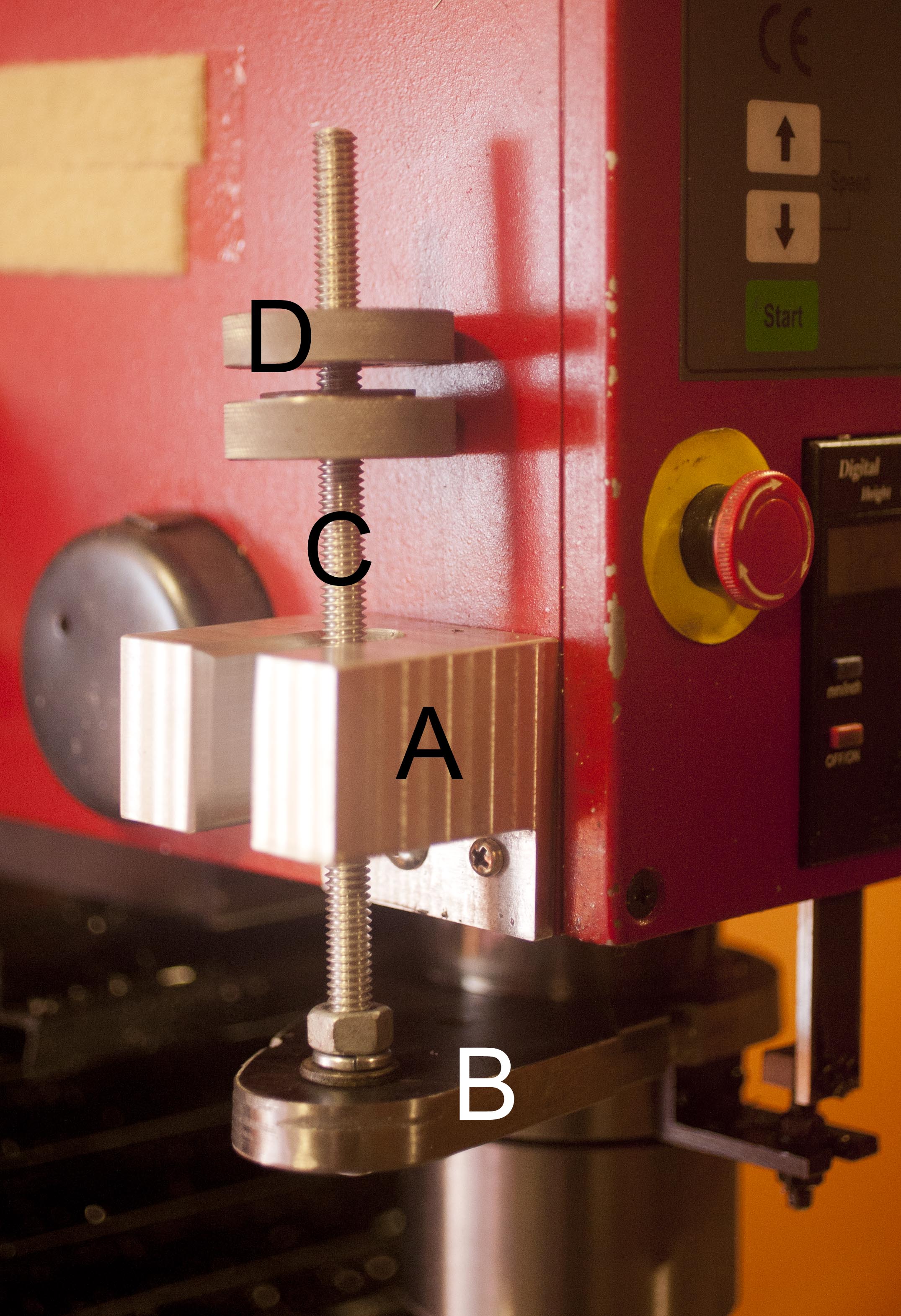
- attaching a bracket (A) with a 10 mm unthreaded hole to the side of the Spindle Box, using the M4 holes freed by the removal of the Protect Cover;
- gripping the Spindle Sleeve (#10), just above the attachment of the Display Fixed Bracket (part #8), with a horizontal beam (B);
- connecting the beam to a vertical threaded rod (C), running upward through the hole in the new bracket; and
- threading a knurled handnut, a washer, and another handnut (D) onto the vertical rod, so that the assembly resembles, in form and in function, the quill stops commonly seen on drill presses.
- addition of X-axis carriage stops, installed trivially by
- attaching a vertical barrier (A) to the Saddle, using the two unused M4 holes found a few inches to the left of the midline; and
- attaching pieces of scrap (B, C) to two improvised 13 × 14 × 6-mm T-nuts, one at each side of the existing T-slot on the front surface of the Work Table (#184).
- addition of a 3-axis digital readout from DRO Pros. My installation of the DRO followed the method used by Dan Kautz for the X and Y axes; I initially installed a 150-mm Y scale, but subsequent failure of the mill's Check Ring 12 (part #167) led to destruction of that scale's read head, and I replaced the scale with a 200-mm unit. For the Z axis, I had to improvise, and I describe my arrangement here; and
- replacement of the shoddy factory-supplied Check Ring 12 with an E-clip made of genuine metal.
![]()
quill stop X-axis stop
replacement parts
Short of dealing directly with Sieg, the only source of replacement parts for the SX3 milling machine may be Little Machine Shop.
Page revised: 03/02/2018 17:31