Chua chaos circuitry and rotation of oscilloscope images
I was intrigued by Web discussion of the Chua chaos circuit, so I built my own, using the design described here. The circuit's three outputs look like independent sine waves, drunkenly amplitude- and frequency-modulated in no clear relation to each other.

Taking any two outputs at a time to a digital oscilloscope in X-Y mode, one usually sees only an uninteresting dot-cloud. The dot-cloud varies as the circuit's potentiometers are tweaked, but it never has any engaging visual structure.
On an analog oscilloscope, the circuit's output is revealed to be a complex path through 3-space. With some settings of the potentiometers, the X-Y patterns are, in the argot of chaos fans, classical strange attractors:


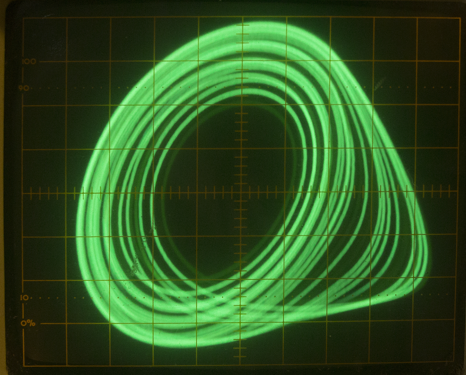

ZGV_13 ZGV_14 ZGV_15 ZGV_16
I was pleased with those results, but frustrated that each of these images made use of only 2 of the circuit's 3 outputs. On the EEVblog forum, I learned of Glen Kleinschmidt's implementation of a device to project a 3-D locus onto the X-Y plane, rotating the incoming data around the X and Y axes by arbitrary amounts, using the elementary trigonometric transformations
x' = x cos θ – z sin θ
y' = y sin Φ – z’ cos Φ
z' = x sin θ + z cos θ
where
θ is the angle of rotation about the y axis
Φ is the angle of rotation about the x axisx' is the horizontal signal for the oscilloscope
y' is the vertical signal for the oscilloscope
z' is an auxiliary variable
Kleinschmidt's device uses a microcontroller to read input controls specifying the angles θ and Φ, to get the trigonometric functions from tables, and to use those values to set digital potentiometers that do the multiplications. To see projections of 3D paths rotating in space, he adapted his device to ignore the input controls in favor of continuous rotation. With these changes, he was able to obtain the stunning videos shown here.
I have experimented with a simpler device, rotating around only one axis at a time. It allows me to choose an axis of rotation:
x' = x, y' = y, z' = z; or
x' = y, y' = z, z' = x; or
x' = z, y' = x, z' = y
and then compute
x'' = x' cos θ – y' sin θ
y'' = z'
where
θ is the angle of rotation about the z' axis
x'' is the horizontal signal for the oscilloscope
y'' is the vertical signal for the oscilloscope
I thought that this simplification would allow me to implement a micro-controller-free device that would generate the sines and cosines in hardware, never explicitly using θ at all. My attempt had only limited success, but the effort was interesting.
The first circuit I came up with uses an XR2206 function-generator chip* to generate sine waves at frequencies in the range of 0.1 to 10 Hz, controlled by a potentiometer. An op-amp differentiator (U402.1 on the schematic) gives the corresponding cosine waves. Then, the calculation of x'' is mostly the work of two AD633 analog multipliers.
What could go wrong with this? The cosines look fine, but — more sophisticated readers will have seen this coming — they are sadly out of phase with the sine waves. The result is that the 3D curves are never fully rotated in space; instead, they gently rock back and forth. Sometimes this motion is enough to give insight into their 3D shape, but sometimes not.
Here and here are two videos of the output. During the videos, I tweaked the potentiometers of the chaos circuit, and once or twice I changed my choice of rotational axis.
I tried again, first feeding better sine/cosine waves (from my Digilent Discovery device and then from a Feeltech FY3200S signal generator) into a bare-bones multiplier circuit to merge the trig functions with the output of the chaos circuitry. This approach was much more successful. With input from "Case Q" of Sprott's taxonomy here, this circuitry produces the charming display shown in this video. Most recently, I've revised the system to compute digital sine/cosine waves with an Arduino; the new multiplier circuit now includes a pair of MCP4725 DAC chips driven by the Arduino's I²C lines. Incidentally, I have several spare (unpopulated) copies of the new multiplier PCB that I'm happy to share.
As described in great detail on his Web site, Kleinschmidt designed and implemented a massive device to generate projections of all 18 of the dissipative Sprott systems. His device uses a special-purpose power supply, and it uses dozens of relays to reconfigure the wiring to model the various systems of equations. It is an impressive, polished, and ultimately intimidating piece of work.
I decided to copy many of his ideas, but using them in a collection of small modules that could be plugged together for the chaotic systems and, probably, for unrelated projects.
For all of my electronics hobby work, the power supply I had been using was a Heathkit IP-2718 unit that I built in 1978 or 1979. It is still functional, but I had become tired of tweaking it into providing a symmetric ±15V supply. Also, I learned from Kleinschmidt that to simulate the Sprott systems, I'd need a wide-ranging (say, ±5V), mV-adjustable auxiliary supply. I built a general-purpose, free-standing power supply to provide these voltages plus a +5V supply that will be handy for other projects. I get unregulated power from a 36VCT transformer and a diode bridge, and then the regulated supplies are provided by this circuit.
Each equation in each of the Sprott systems expresses a derivative (dx/dt, dy/dt, or dz/dt) as a simple function of x, y, z and some constants. In Kleinschmidt's device, simulating each such equation involved only (at most) multiplication, integration, and inversion. I designed little modules for each of these functions, and I built several copies of each module. Simulating one of the Sprott systems entails connecting modules together. With three modules of each kind fixed on a base and semi-permanently wired for power, the remaining wiring is not onerous, although of course I cannot just flip back and forth, as Kleinschmidt can, among the various Sprott systems.
To a great extent, each of my modules simply copies a portion of Kleinschmidt's big device. The multiplier module is build around an AD633 multiplier IC; most of the module is devoted to trimming circuitry and to pass-through connections so that power connections can be daisy-chained. The integrator and inverter modules are similar, but simpler. Because the logic of the simulations often requires that input be provided through a 10K resistor, each of the integrator and inverter modules provides an input connector that includes such a resistor within the module.
With the modules connected as shown here, these videos show simulations of Sprott system H, I, and L, respectively.
Different small offsets to the integrator modules can cause a given one of the Sprott systems to find dramatically different attractors. Sprott system B, for example, is responsible both for this bland attractor and this bizarre one.
* Yes, there are other ways to generate sine waves in simple hardware. I had had the XR2206 sitting around for 35 years, so I thought it was time to get some use out of it.
Page revised: 01/27/2017 13:37